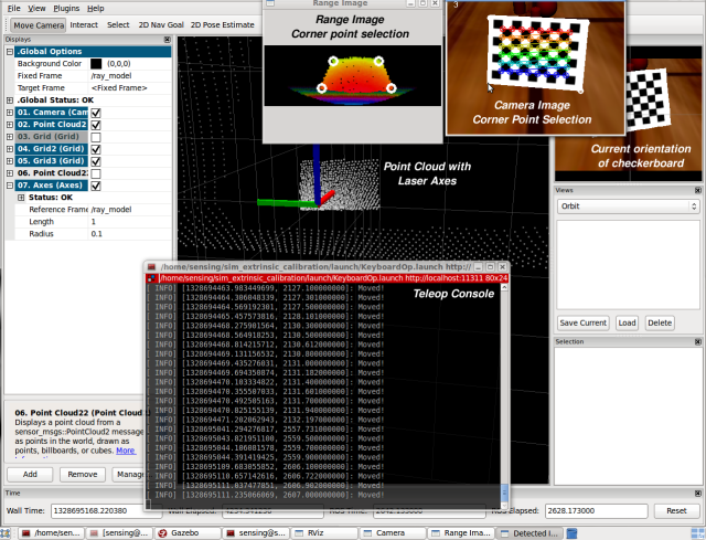
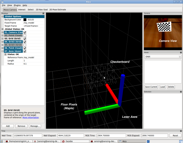
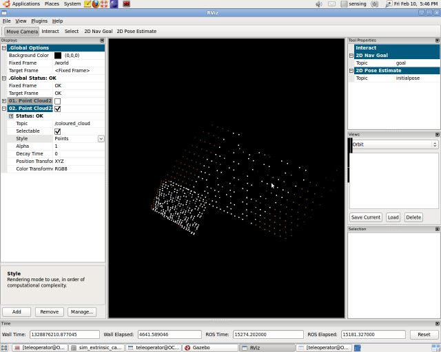
So, as I mentioned in my previous post, I am working on recreating a 3D photorealistic environment by mapping image data onto my pointcloud in realtime. Now, the camera and the laser rangefinder can be considered as two separate frames of reference looking at the same point in the world. After calibration, i.e. after finding the rotational and translational relationship (a matrix) between the two frames, I can express (map) any point in one frame to the other. So, here I first project the 3D point cloud points onto the camera’s frame of reference. Then, selecting only the indices which fall within the range of the image (because the laser rangefinder has a much wider field of view than the camera. The region that the camera captures is a subset of the region acquired by the rangefinder. So, I’ll get corresponding indices, say from negative coordinates like (-200,-300) to (800,600) for a 640×480 image) Hence, I only need to colour the 3D points which lie within the (0,0) and (640,480) indices using the RGB values at the corresponding image pixel. The resultant XYZRGB pointcloud is then published, which is what you see here. Obviously, since the spatial resolution of the laser rangefinder is much less than the camera’s, the resulting output is not as dense, and requires interpolation, which is what I am working on right now.
Head on to the images for a more detailed description. They’re fun!

So here, first I create a range image from the point cloud, and display it in a HighGUI window for the user to select corner points. As I already know how I have projected the 3D laser data onto the 2D image, I can remap from the clicked coordinates to the actual 3D point in the laser rangefinder data. The corresponding points are selected on the image similarly, and the code then moves onto the next image with detected chessboard corners, till a specified number of successful grabs are accomplished.

Here's a screenshot of Rviz showing the cloud in action. Notice the slight bleed along the left edge of the checkerboard. That's because of issues in selection of corner points in the range image. Hopefully in the real world calibration, we might be able to use glossy print checkerboard so that the rays bounce off the black squares, giving us nice holes in the range image to select. Another interesting thing to note is the 'projection' of the board on the ground. That's because the checkerboard is actually occluding the region on the ground behind it, and so the code faithfully copies whatever value it finds on the image corresponding to the 3D coordinate.


